2022年1月27日星期四

How to adjust the parameters to make better use of the spectrum analyzer

The simplest and most intuitive purpose of using a spectrum analyzer is to find and observe the spectrum signal within the range, and even to save it for further digital processing or analysis. Therefore, except of basic settings such as center frequency and sweep width, only reasonable setting of VBW, RBW and other parameter can obtain more real and accurate signals.

1. RBW

The FFT bin in the frequency domain, or the Resolution Bandwidth (RBW), determines the frequency resolution of the signal that can be resolved and analyzed by the spectrum analyzer. For example, if a larger FFTbin or smaller RBW range is set, then spectrum analyzer can observe and analyze more details of the signal. If a higher sensitivity is desired, user needs to turn down RBW, so as to lower the noise level to ensure that the signal is not drowned by noise. On the other hand, lowering the RBW also reduces the speed of each sweep, so there is a tradeoff between sweep resolution and test speed.


In addition, power is found less than some dB when use spectrum analyzer to test the maximum power. In this situation, some users maybe think that spectrum analyzer is not calibrated or something wrong with it. But most likely the setting for RBW is not reasonable.

RBW determines the number of collection points in the sampling process. When the sampling points are few (RBW is large), it is likely that the peak value of the signal falls between the two frequency points, resulting in that the captured peak power is not the actual value.


2. VBW

Except of RBW, Video Bandwidth (VBW) filters digitally filtering and process signal output by FFT engine and carry out smooth process to signal amplitude.

The video bandwidth reflects the bandwidth of the video filter behind the envelope detector in the spectrum analyzer receiver. This filter also affects the display noise, but unlike the way bandwidth is resolved, in a video filter the average level of noise remains constant but the variation of noise is reduced. Therefore, the role of the video filter is to "smooth out" the noise of the signal, so changing the VBW does not improve the sensitivity, but when measuring low power signals, the VBW improves the recognition and reproducibility, with a smoother test curve but a corresponding increase in scan time.

If spikes from phase-locked loop (PLL) or intermodulation distortion products may overwhelm the signal of interest, and lowering the RBW will lower the noise baseline, and lowering the VBW will further smooth the remaining noise, then the spectrum analyzer can reveal precise measurements of previously hidden signals.

3. AMP

Low Noise Amplifiers (LNAs), or preamplifiers (AMPs), are generally divided into RF front-end Amplifiers and mid-frequency Amplifiers, all are used to amplify the signal appropriately for a subsequent processing. If the signal power is very low, the ADC may not be able to adequately process it after the preselected or mid-frequency filter, increasing the gain of the preamplifier can make the signal reach enough level to be collected and processed. There are various types of preamplifiers available. 

4. ATT

Attenuator (ATT) plays the opposite function compared with the amplifier. When measure a signal with higher level, to protect spectrum analyzer not be damaged, this signal must be attenuated, as well as get a larger dynamic range through adjusting the attenuator into the mixer level.

In addition, turn down the noise level value if adjust the attenuator to lower so as ensure the signal is not drowned by noise to improve the sensitivity of spectrum analyzer.

When use spectrum analyzer to observe and capture required signal, it is necessary for user to adjust according to the signal characteristics and try every parameter according to needs. So reasonable use of spectrum analyzer can ensure a better observe effect.

2022年1月19日星期三

New Launch--TFG2900A Series Function/Arbitrary Waveform Generator

New Launch--TFG2900A Series Function/Arbitrary Waveform Generator


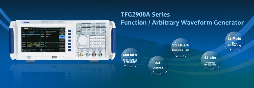
In 2020 year, Suin launched its 4 channels function/arbitrary waveform generator TFG2900A series. The 4 channels are independent and have complete equivalent functions. With 1ppm frequency accuracy, 1μHz frequency resolution, and Sine, Square, Exponential, Log, etc. 165 kinds waveforms. It can output 13 modulation signals, such as FM, AM, PM, PWM, SUM, FSK, ASK, etc. At the same time, it also has burst, sweep, waveform editing, etc. functions.

With above characteristics, it must be a good instrument in your everyday work.

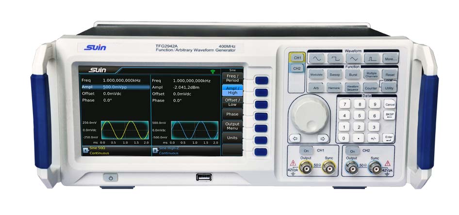
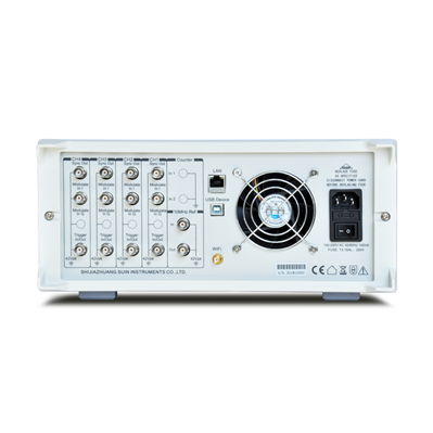
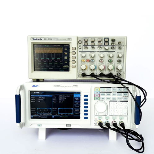
Please see its outlook pictures and working pictures as follows:

New Launch--TFG2900A Series Function/Arbitrary Waveform Generator

TFG2900A Front Panel


image.png

TFG2900A Rear Panel


image.png

4 channels working demo


image.png

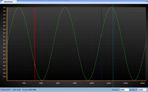
Waveform Editing


image.png


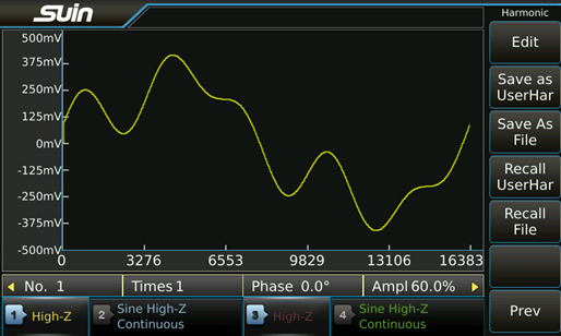
Harmonic Function


If you want to learn more detailed specifications, please visit Home—Products—Signal Generators—Function/Arbitrary Generators in www.suindigital.com or contact us directly.


2022年1月12日星期三

SK3323/3325/3503 Sk3323 Power Supply

programmable linear DC power Feature

The SK33XX series programmable linear DC power supplies have three independent outputs – two sets of adjustable voltage/current and a fixed set of selectable voltage1.8V, 2.5V, 3.3V and 5V. it has three available operation modes–independent, series and parallel modes. All make this series become a high performance-to-price ratio instrument.


Aplication

Military R&D, Quality detection, Circuit test, Test of industrial manufacture automatization,

Education and Technical Training, Test of electronic assemblies, Aging test


Design Feature

1. 3 independent outputs-two 32V or 50V /5.1A or 3.2A, one 1.8V, 2.5V, 3.3V, 5V/3.2A, maximum 342W.

2. 4 digit voltage and current display, minimum resolution-10mV, 1mA

3. Smart temperature controlled fan to reduce noise effectively.

4. Save/Recall 5 group system set-ups

5. Standard timing output

6. Comprehensive over-voltage protection


Specifiations

Model

SK3323

SK3325

SK3503

Channel

CH1

0~32V/

0~3.2A

0~32V

/0~5.1A

0~50V/

0~3.2A

CH2

0~32V/

0~3.2A

0~32V/

0~5.1A

0~50V/

0~3.2A

CH3

1.8V/2.5V/3.3V/5.0V switchable,

3.2A (Max. output)

Line Regulation

Voltage

CH1, CH2

≤1×10⁻⁴+2mV

CH3

≤1×10⁻⁴+3mV

Current

CH1, CH2

≤1×10⁻⁴+2mA

Load Regulation

Voltage

CH1

≤1×10⁻⁴+3mV

≤1×10⁻⁴+8mV

≤1×10⁻⁴+3mV

CH2

CH3

≤1×10⁻⁴+3mV

Current

CH1, CH2

≤1×10⁻⁴+2mA

Programming/

Readback             Accuracy

Voltage

CH1

≤±(0.5%+30mV)

≤±(0.5%+60mV)

CH2

CH3

(no

readback)

≤±7%

Current

CH1

≤±(0.5%+30mA)

≤±(1%+60mA)

≤±(0.5%+30mA)

CH2

CH3

(no

readback)

≥3.2A

Ripple and Noise

Voltage

CH1, CH2

≤1mVrms

≤1.5mVrms

CH3

≤1mVrms

Current

CH1, CH2

≤3mArms

≤5mArms

≤3mArms

Display

resolution

Voltage

CH1, CH2

10mV

Current

CH1, CH2

1mA

Display Digits

Voltage

4 digits

Current

4 digits

Other function

Auto switch of serial and parallel

General

Characteristics

Rated Voltage

AC220(1±10%)V

Rated Power

500W 670VA

600W  800VA

Rated Frequency

50/60(1±5%)Hz

USB charging Interface

5V 1A

Remote Interface

USB, LAN (option)

Dimension

226×140×303mm3

226×140×333mm3

Weight

8KGs

9KGs


Standard Accessories

Power Cord:1pcs

CD( User's Guide):1pcs


Options

LAN


https://www.suindigital.com/DC_power_supply/838.html


2022年1月4日星期二

SS7406 Frequency Counter Stopwatch Calibrator Wholesale

SS7406 Frequency Counter     Stopwatch Calibrator Wholesale       Universal Frequency Counter


Overview

SS7406 frequency counter / timer / analyzer packs the functionality of a frequency counter, frequency meter and timer into one feature-rich instrument. With higher resolution, you can capture very small frequency and time changes. Meantime it offers comprehensive analysis modes, including measurement statistics, histograms, and trend chart.


Applications

Test & Measurement, R&D, education, production


Design Features

Two 200MHz general-purpose channels

Typical 25ps single-shot time resolution

11 digits/s frequency resolution

Optional 5×10⁻¹⁰/day high-stability time base

4.3' TFT-LCD display to show abundant information

Firm and sophisticated standard 2U design

Standard interface of RS-232, GPIB and LAN


Standard Accessories

Power Cord:1pcs

BNC Testing cable:1pcs

CD(Software+ User's Guide):1pcs


https://www.suindigital.com/frequency_counter/908.html

How to Measure Adjacent Channel Power with a Spectrum Analyzer?

Adjacent channel power, as the name suggests, measures the power of the left and right channels (also known as upper and lower channels) adj...