2022年7月30日星期六

How to Test the Frequency Response by SA1140C Frequency Characteristic Analyzer?

In electronic testing, we always need to test the resistance characteristic and transmission characteristics of the electric circuit. Transmission characteristic includes gain and attenuation, amplitude-frequency characteristic, phase-frequency characteristic, etc. The instrument to test these characteristics is called a frequency characteristic analyzer, simply named frequency sweeper. It is really a good helper for adjusting, calibrating, and troubleshooting the electric circuit not only in education but also in research and development. 


Now we’ll take SA1140C Frequency Characteristic Analyzer as an example to demonstrate how to test the frequency response of an RC circuit.


Before testing, SA1140C should be calibrated firstly by pressing [CAL] key, then set as follows:

• Output gain   -30dB

• Start             5kHz

• Stop             100kHz 

• Impedance    500k


And then connect the RC circuit as below picture shown: 

• C=15 nF   

• L=4.7mH   

• f=20.200kHz
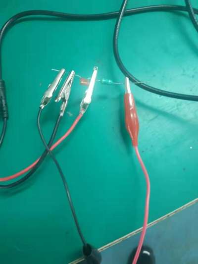

How to Test the Frequency Response by SA1140C Frequency Characteristic Analyzer?cid=191


The measuring result will be displayed in SA1140C as below picture:
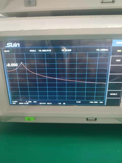

frequency characteristic analyzer


You can also measure the frequency response of the LC resonance circuit or low pass filter according to the above set and operation.


If you want to know more about the SA1140C Frequency Characteristic Analyzer, please check its specification on Suin website or contact us directly.
2022年7月22日星期五

New Launch - TFG3836 3.6GHz RF Signal Generator

Suin launches new RF signal generator TFG3836 at the beginning of this March after market research and engineers’hard work.


RF signal generator is the instrument that’s especially used to produce RF signal, currently, most vector signal generators are also in RF band, so it’s called vector RF signal generator. Generally speaking, the simple RF signal generator is used to perform carrier tests while the vector signal generator is mainly for the digital signal tests.


When choosing the RF signal generators, factors such as frequency range of output signal, modulation type, frequency stability, amplitude accuracy, required power size, etc should be considered. According to this, let’s see the features of TFG3836.


1. Frequency range up to 3.6GHz


2. Wild range of level output

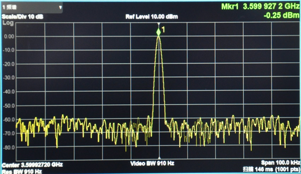
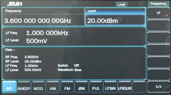
The maximum output level up to +13dBm (nominal value), maximum +20dBm is settable to meet the nonlinearity test of the amplifier.


图片1_副本.png


3. Higher level accuracy

The typical accuracy of output level could be up to 0.5dB, which could provide the user with accurate excitation signals.


图片2_副本.png


4. Lower phase noise

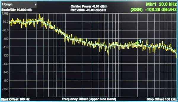
Higher signal purity and the typical phase noise can reach < -105dBc/Hz@20 kHz. The better the high-stability clock reference is selected, the better phase noise capability will get.


图片3_副本.png


5. Full frequency and power sweep capability


6. Rich modulation function

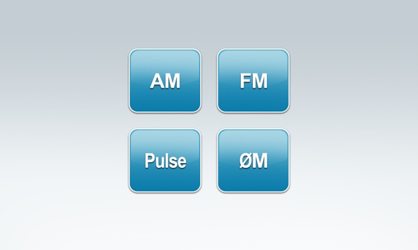
Provides standard AM, FM, φM, and Pulse modulation, all supporting internal and external modulation.


图片4_副本.png


7. Powerful pulse modulation function

A high-quality pulse modulated signal could be provided. The typical rise/fall time could be 10ns and an on/off ration greater than 70dB. Both internal and external modulation can be supported. The built-in pulse generator could generate pulse sequence and output it as a separate pulse generator


8. Multi low-frequency output

DC, Sine, and Square can be output from the LF port to be used in different simulation tests. At the same time, the LF signal is independent of the internal modulation signal, which equals to provide two independent RF and LF signal generators to the application.


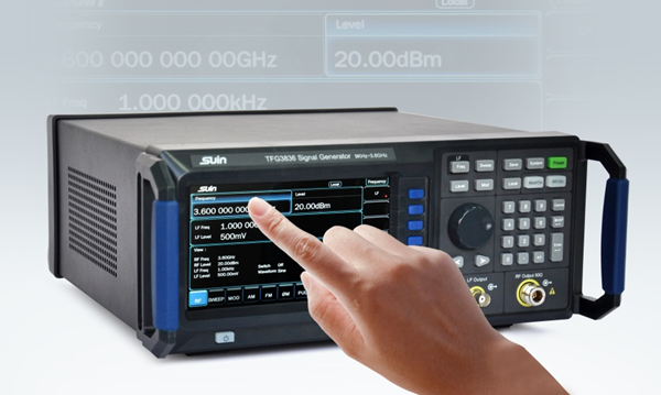
9. 7 inches TFT capacitive touch screen, simple and easy to operate.


RF Signal Generator


All mentioned functions are standard configurations, also supplied with the most competitive price. Compared with similar products in the current market, TFG3836 will be a better choice for educational laboratories, industrial production lines, R&D applications.

2022年7月15日星期五

SA9275 RF Spectrum Analyzer and Its Measuring Function


What is Spectrum Analyzer?

Spectrum Analyzer is fundamentally a testing instrument that measures various parameters in a circuit or in a system at radio frequency range. A piece of normal testing equipment would measure the quantity based on its amplitude with respect to time. For example, a voltmeter would measure the voltage amplitude based on the time domain. So we will get a sinusoidal curve of AC voltage or a straight line for DC voltage. But a spectrum analyzer would measure the quantity in terms of amplitude versus frequency.

Suin has developed an RF Spectrum Analyzer with model SA9275, with the high frequency and low DANL, it can measure max 7.5GHz signal, besides the normal function such as frequency, amplitude measurement, it has advanced measurements like channel power, adjacent channel power, N-dB bandwidth, occupied bandwidth, etc. And below are the detailed applications of it.


Main Measuring Function of SA9275 RF Spectrum Analyzer

Looking at the frequency spectrum of a signal to see items like the following:

The overall spectrum of a modulated signal to see whether it is wide enough or too narrow, etc. If it is too wide then it could cause interference to users in adjacent channels. An example is as below picture shown.


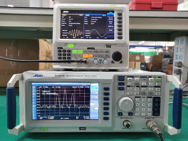
3.2GHz/7.5GHz RF Spectrum Aanalyzer


This picture shows Suin SA9275 Spectrum Analyzer measures an AM signal, with carrier wave frequency 20MHz, Modulate frequency 30kHz, and modulate depth 50%.

To investigate whether any spurious or unwanted signals are present. These signals could cause interference to users as other frequencies of signals are transmitted.

To find out whether a signal is on the right frequency, and not in another band.

To measure the phase noise on a signal.

Besides that, the SA9275 RF spectrum analyzer can be also used when undertaking EMI measurements. The analyzer can be used to locate the frequency and nature of the signal that may be causing an issue. Contact us now for a quote on the SA9275 RF spectrum analyzer!

2022年7月7日星期四

TFG6800 Series Arbitrary Waveform Generator in Educational Solutions

Along with the science development, more and more electronic engineers are needed in the future. University and colleges require to configure the whole set of electronic test and measurement equipment to help their student to learn the basics of measurements so as to shape their future in engineering.

Suin Instruments can provide the fundamental teaching lab equipment from function/arbitrary waveform generators to dc power supplies and universal frequency counters, etc.

TFG6800 Series Arbitrary waveform generator can be a great choice for university teaching because it has a small size and accurate measurement compared to the conventional expensive and bulky signal generator. With the strong function of modulating, burst, waveform sequence, harmonic, etc., students can not only know how to use the generator to generate a required signal but also deeply understand the circuit design. 


TFG6800 Series Arbitrary Waveform Generator

Pict 1


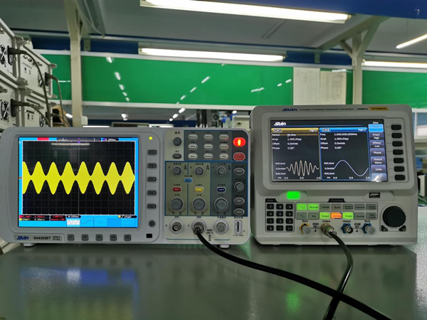
If a modulated signal, such as AM/FM/PM needs in the teaching experiment, TFG6800 can realize it by setting the frequency period, amplitude, offset, etc., like Pict 1 shown.

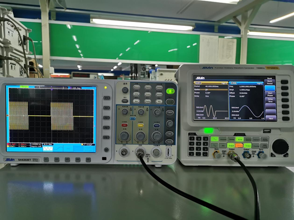
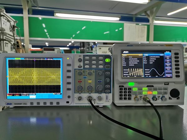
Not only modulate signal can be realized, but also Burst, Sweep, Harmonic signal can be output like Pict 2, Pict 3 shown.


TFG6800 Series Arbitrary Waveform Generator

Pict 2


TFG6800 Series Arbitrary Waveform Generator

Pict 3


With features of dual channels, 100MHz bandwidth, 16 bit vertical resolution, 20ppm accuracy, and 165 kinds of built-in waveforms, the TFG6800 Series arbitrary waveform generator can generate all kinds of waveforms with more accuracy which is needed in the teaching lab. Small size, lightweight make it more flexible in the class. 7'' LED touch screen can make operation more easily and show the values and waveform directly.


Until now, many universities have used TFG6800 Series Arbitrary waveform generator in their teaching experiment. Welcome to contact Suin if you want to know more information about it.

How to Measure Adjacent Channel Power with a Spectrum Analyzer?

Adjacent channel power, as the name suggests, measures the power of the left and right channels (also known as upper and lower channels) adj...