2023年5月7日星期日

SA2200 Introduction - Portable Harmonic Measurement Tool

In order to keep the harmonic content and waveform distortion rate in the power supply system within the specified values, it is necessary to know the actual harmonic content in the grid, which can be calculated by theoretical analysis and actual measurement. The application of a large number of nonlinear loads has resulted in increasing content of high harmonics in the power grid. However, the complexity of harmonic problems in the power grid and the difficulty of accurate analysis make the actual measurement more important, which requires reliable and accurate measurement devices.


Our power quality analyzer SA2200 has a relatively perfect harmonic measurement function, the handheld is more portable, and this instrument can monitor AC and DC line disturbances through four channels. it integrates capture, record, analysis, display, can measure and analyze total harmonic distortion of voltage and current, and can measure and record harmonics up to the 100th.


In order to meet the different analysis requirements of customers, we set two modes: Bar Graph and Table.


The bar graph shows the percentage contribution of each of the components related to the fundamental or full signal. A signal without distortion should show a 1st harmonic at 100% while the others are at 0; in practice, this will not occur because there always is a certain amount of harmonics resulting in distortion.
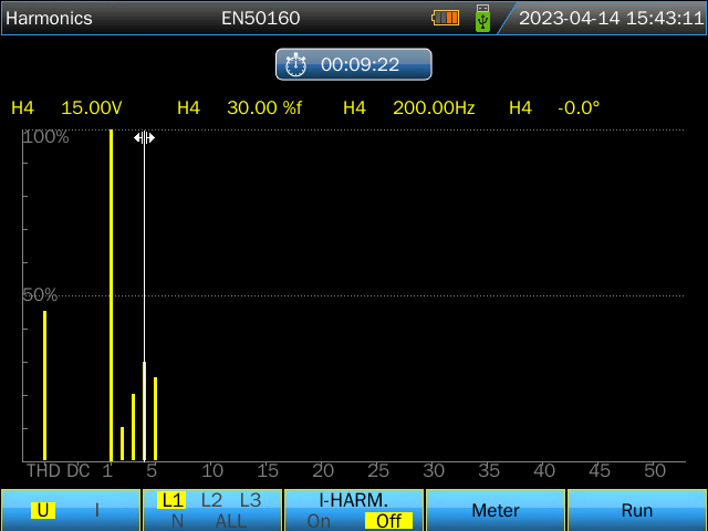

Bar Graph


Figure 1.  Bar Graph


The table screen lists all the harmonic parameters, including Harmonic Voltage, Harmonic Current, Inter-harmonic Voltage, and Inter-harmonic Current.
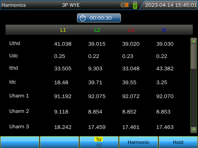
 

Table


Figure 2. Table

2023年4月18日星期二

Introduction And Measuring of Active Power And Reactive Power


What is active power?


Active power is the power to make the machine working, in another word, the electric power to transfer electric energy to other mode energy, such as mechanical energy, optical energy, heat energy, etc.

For example, 5.5kW motor can transfer 5.5kW electric energy to mechanical energy so as to make water pump to pump water or make thresher threshing.


What is reactive power?


Reactive power is a little abstract, it is mainly used in the exchange between electric field and magnetic field in the electric circuit, also establishing and maintaining magnetic field in the electrical equipment. It doesn’t make any power externally, but transform to other mode energy. Electrical equipment with electromagnetic coils needs to consume reactive power to establish magnetic field.

For example, 40W fluorescent lamp needs not only over 40W active power to make light (ballast also needs to consume parts of active power), but also almost 80Var reactive power to make the ballast’s coil establish alternating magnetic field.


Relationship between active power and reactive power


The rotating magnetic field needed by the motor running is established and maintained by reactive power. It can make motor rotate, and make the machine running so that mechanical energy is transformed by electrical energy.

Transformer working also needs reactive power to make primary coil generate magnetic field, secondary coil induces a voltage.

In summary, all electrical equipment with electromagnetic coil need to establish magnetic field to work, whereas the consuming energy to establish and maintain magnetic field comes from the reactive power.

Without reactive power, motor can’t rotate, transformer can’t work, electric reactor and relay can’t work either. If the magnetic field in the electrical equipment can’t be established, the equipment can’t work either.

Thus besides active power, the power system also needs to supply reactive power to make electrical equipment run.


SA2200 Power quality analyzer has the active power and reactive power measuring function, which will help users to calculate and reduce the power consumption. Please kindly check the measuring data as below:

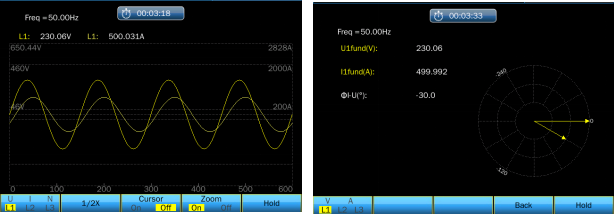
Output signal: frequency 50Hz, voltage 230V, current 500A, current phase lagging voltage phase 30°(inductive load)


Introduction And Measuring of Active Power And Reactive Power


Figure1. the output signal shown in SA2200 Scope mode and Unbalance mode.


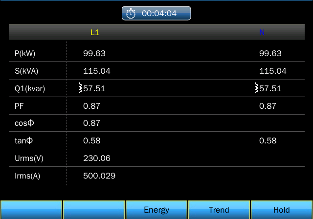
Then press [Power&Energy] to measure as Figure 2 show.


Introduction And Measuring of Active Power And Reactive Power


Figure2.


Thus we know the measured active power is 99.63kW, fundamental reactive power is 57.51kvar, which can be a reference for the reactive power compensation capacitor selection.


Note:

P(kW): active power

S(kVA): apparent power, the product of Vrms and Irms

Q1(kvar): fundamental wave’s reactive power

PF: power factor, ratio of active power and apparent power

cosФ: displacement power factor, cosine value of the angle of fundamental current and fundamental voltage

tanФ: ration of reactive power and active power

Urms: rms voltage

Irms: rms current

2023年3月31日星期五

How to Track EMI Emission Source by Spectrum Analyzer

Spectrum analyzer is a more suitable instrument for measuring EMI. Spectrum analyzer is the instrument displaying voltage amplitude change with the frequency and its waveform called spectrum. Spectrum analyzer overcomes the shortcomings of oscilloscope in measuring EMI and it can accurately measure the EMI at each frequency and directly display the signal spectrum components.

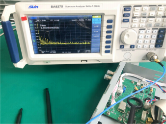
Below is the introduction of how to use nearby probe and spectrum analyzer SA9275 or SA9115 to test nearby EMI.

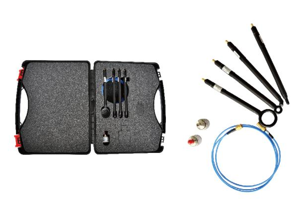
Nearby probe includes: EMI electric field probe and EMI magnetic field probe.


Nearby Probe Set

Figure 1. Nearby Probe Set


Test methods:

Set spectrum analyzer's sweep range and analyzing bandwidth according to the interference frequency.

The corresponding relationship between sweep range and analyzing bandwidth are as follows:


Sweep range

Analyzing bandwidth

9kHz~150 kHz

200Hz(6dB)

150kHz~30MHz

9kHz(6dB)

30MHz ~1GHz

120kHz(6dB)

>1GHz

1MHz(3dB)


To set the Spectrum analyzer's sweep range, you need press【FREQ】firstly and then set Starting frequency and Stop frequency.

To set the analyzing bandwidth, you need to press【BW】firstly, and then input the needed bandwidth which should be within the range of this instrument.


SA9275 EMI Test

Figure 2. SA9275 EMI Test

SA9115 EMI Test

Figure 3. SA9115 EMI Test

2023年3月15日星期三

How to Use Bench-top Digital Multimeter?

Multimeters are one of the necessary instruments for hardware engineers, they can measure voltage, current, resistance, capacitance, diode, etc. Nowadays, portable multimeters and clamp multimeters as common ones in the market, and it is rarely known by people how to use bench-top multimeters. Now we'll briefly introduce it by taking Suin SA5053 digital multimeter as a sample. Hope it will do some favor in your everyday's testing and measuring work.

The using method of bench-top multimeters and portable multimeters has some differences, although the basic principle is the same. Actually, it is very easy to use bench-top multimeters. There is a red terminal in the red testing lead, and a black terminal in the black testing lead, which is the same with common multimeters, red test lead is positive polarity, black test lead is negative. This test lead kit will be used during parameter measuring.

Before using it, the Null setting is the first step to do which is can't be ignored. Then choose the suitable parameters to test according to the under-tested component or instruments. Eg., to test DC voltage, the DCV function should be chosen in SA5053, while not other functions like DCI, ACI, resistance, or capacitance. Please be noted to choose the suitable voltage range to test. If the voltage of the under-tested instrument is out of range, SA5053 can't display the testing result and may be burned. After everything is set OK, contact the positive and negative polarity by red and black test lead kit stably, and the measuring result will be shown in the SA5053.

Some tips for users when using digital multimeters are as followings:

1. Please read User's Manual carefully before using it to learn the function keys and measuring range.

2. Make sure to set suitable function and range, input voltage or current shouldn't be surpassed the maximum range to protect the internal circuit from being damaged.


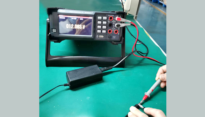
SA5053 testing power adapter's voltage

Figure 1. SA5053 testing power adapter's voltage


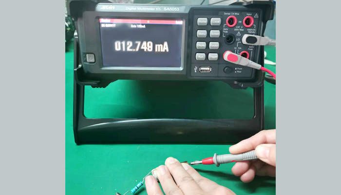
SA5053 testing current

Figure 2. SA5053 testing current


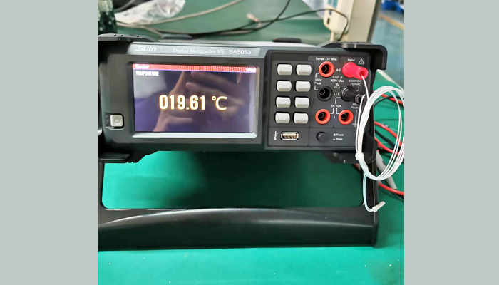
 SA5053 testing temperature

Figure 3. SA5053 testing temperature


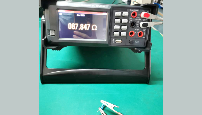
SA5053 testing resistance 

Figure 4. SA5053 testing resistance


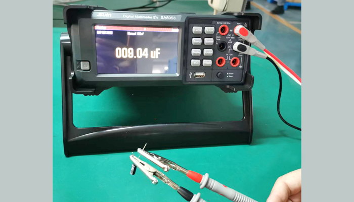
SA5053 testing capacitance

Figure 5. SA5053 testing capacitance


Please contact Suin for more information about SA5053 digital multimeter.

2023年2月28日星期二

Choose a High Cost-performance RF Signal Generator

Nowadays many brands of rf signal generator are existing in the market, it will make double results with half work by selecting a suitable product in your test and measuring work.

Firstly, we need to know the difference between analog rf signal generator and vector rf signal generator.

Analog rf signal generator mainly generate single frequency point signal, sweep signal, RF pulse(single or double), AM/FM/PM analog modulation signal, but can't produce PSK/QAM digital modulation signal.

Vector rf signal generators not only have all the functions of analog ones, but also can produce PSK/QAM digital modulation signal, chirp pulse, Barker code Pulse modulation signal.

Vector ones have better functions than analog ones, which means the price of it will be much higher than analog ones. In the same frequency range, analog ones have better price than vector ones and it can be up to 67GHz high with external frequency doubler which can't be acquired by vector ones.

For laboratories, product development and researchers, education, etc., analog ones are more popularly used than vectors ones. Their performance and functions need to be compared during selection. Suin TFG3836 as an economical analog rf signal generator, has both sweep and modulation function, frequency measuring range higher to 3.6GHz, ultra low phase noise can make better measuring experience you've never met, which will be the best choice for your real measuring work.

Below are the main characteristics demo:


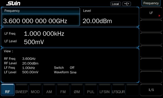
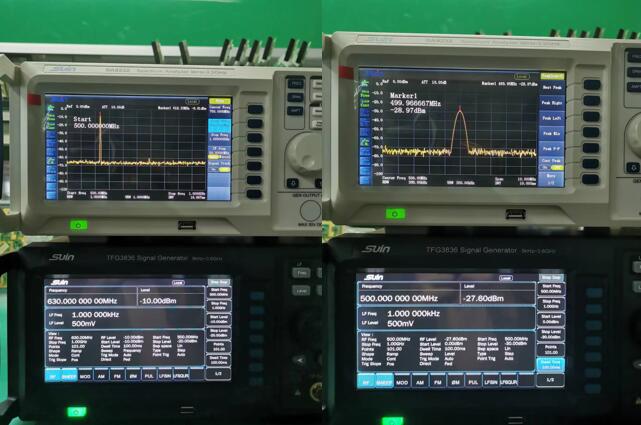
Fig.1 Max 3.6GHz frequency measuring range, 20dBm Level


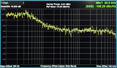
Fig. 2 Low phase noise <-105dBc/Hz@20kHz typical


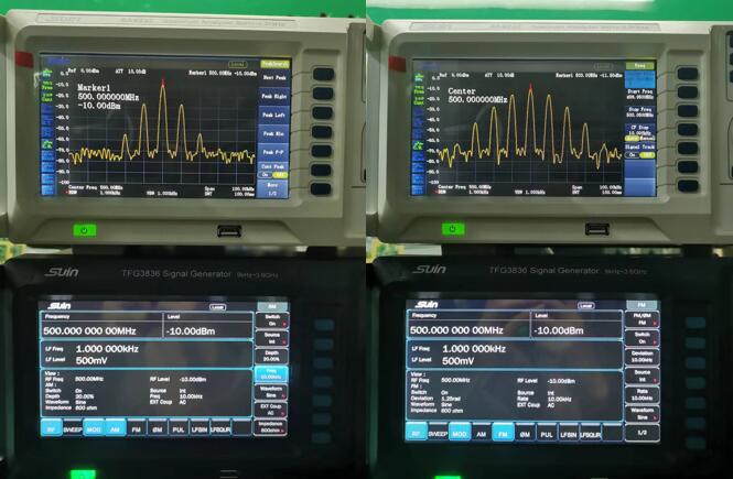
Fig. 3 Frequency and Level sweep function


Fig. 4 AM and FM modulation


If you have any question about TFG3836, welcome to contact us.

2023年2月15日星期三

Handheld Multimeters VS Bench-top Multimeters

Digital multimeters are electronic test instruments with versatile usage, forms, and types which may be more than other kinds of instruments. The most common ones are handheld and bench-top multimeters. Here we would like to share some tips during your selection.


Handheld multimeters' advantage is that it is easy and quick to test voltage, current, and resistance from one position to another. In this condition, battery life, durability, and size are more important than resolution, accuracy, measuring speed, or connectivity with the PC.


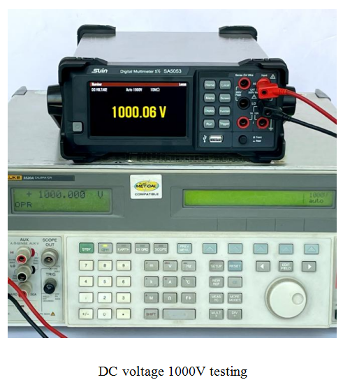
Bench-top multimeters have a larger size than handheld ones because they are mainly used in platforms of engineers or automation systems. All instructors in engineering, researchers, product designers, and all testing engineers are the users of bench-top ones. For these users, characteristics like sensitivity, accuracy, large measuring range, maximum functions, measuring speed, and connectivity with PC are more important factors. SA5053 digital multimeter can measure max DC Voltage 1000V with 0.01% accuracy, and AC Voltage 750V with 0.1% accuracy, which can meet most engineers' requirements.


DC voltage 1000V testing


Bench-top types have more communication interfaces like RS-232, GPIB, USB, LAN, etc., which can easily connect with computers and other instruments to remote control multimeters and send or receive data.

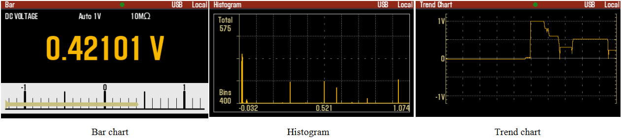
Automation system always requires rapid measuring speed and can acquire flexible waveforms, SA5053 is designed to have these functions--bar chart, trend chart, and histogram displaying as below picture shown. If the repair technician's main work is to make the electronic system run normally, he doesn’t need this function. But it is more important to researchers, designers, and testing engineers that which can help them get a larger measuring range, higher accuracy, and some vital small transient signals, which can even provide additional advantages and then help you to design instruments with better performance than their competitors.


Bar chart,Histogram,Trend chart


Meantime, rich measuring functions such as DC Voltage/Current, AC Voltage/Current, 2 wire/4 wire resistance, frequency, period, capacitance, diode, continuity, temperature, and Math function also make bench-top multimeters widely used in production tests, on-site maintenance, fixed point repairing, research and development, education, etc.


Welcome to contact us for more information about SA5053 multimeters.

2022年11月9日星期三

Brief Introduction of SS7000 Series Universal Frequency Counter/Timer/Analyzer

What's a frequency counter? It is an electronic test instrument especially made for signal frequency measuring and is mainly composed of a time base circuit, input circuit, frequency display circuit and control circuit.

Along with the development of technique and R&D capability, the instruments made by China perform more and more excellently than that made overseas. Here we'd like to introduce the main functions through Suin SS7000 Series frequency counter as below.


1. Frequency measuring


Frequency is the number of waveform vibrations in the unit of time, which is the reciprocal of the period and the basic measuring parameter.

SS7000 Series frequency counter/timer/analyzer can not only measure frequency in the range of 200MHz, but also measure rf and microwave signals with high-frequency channel options, such as 3GHz, 6.5GHz, highest up to 40GHz to meet advanced measuring requirements.


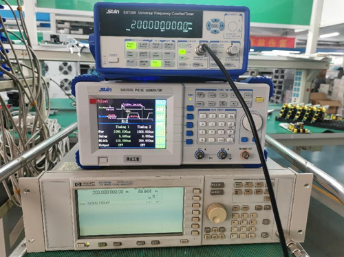
200MHz frequency measuring

Fig.1. 200MHz frequency measuring


2. Period measuring


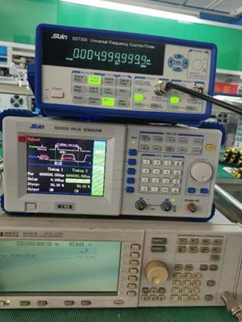
The period is the time for one time waveform vibration, which is the reciprocal of the frequency. Most of the frequency counters have this function. For SS7000 Series, it can measure period range 5ns-1000s.


Period measuring

Fig. 2. Period measuring


3. Time interval measuring


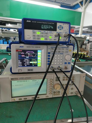
Time interval is the time measurement from the start signal to the stop signal. Usually start signal is input into CH1, the stop signal to CH2, and it will measure the time interval from CH1 to CH2. Time resolution is the main parameter to evaluate the performance of the instrument. The normal time resolution for the SS7000 Series is 2.5ns, and the highest can be up to 25ps. High resolution is most important in areas of time-frequency transmitting and measuring, aerospace, radar positioning, laser distance measuring, etc. It requires a frequency counter have at most two channels.


 Time interval measuring

Fig. 3. Time interval measuring


4. Pulse width measuring


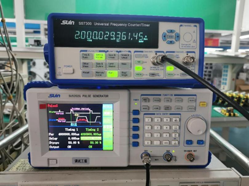
Pulse width, pulse amplitude and pulse shape are the main parameters for the pulse signal. Pulse width is the time difference between two points in the 50% pulse amplitude. It can indicate the duration time for the pulse energy. Most frequency counters can measure positive and negative pulse width. SS7000 series can measure pulse width range 30ns-5000s and 1ns-10000s.


 Positive pulse width measuring

Fig. 4. Positive pulse width measuring


5. Duty cycle measuring


The duty cycle is the rate of the time when the signal is at a high/low level to the total signal time, which can also be expressed as the rate of a single pulse to a period. When other parameters are the same, the more duty cycle is, the higher energy the signal has. SS7000 Series can measure duty cycle range 1%-99%.


Duty cycle measuring

Fig. 5. Duty cycle measuring


6. Totalize measuring


Totalize is the simple counting of events. It is useful in areas of counting electronic events or physical events or automatic measuring which needs digital results. When the frequency counter is doing the totalize and displaying it, the gate circuit opens.


7. Phase difference measuring


Phase difference, also called phase displacement, is the phase difference between two signals with the same frequency, indicating the two signals leading or lagging relationship in time.


8. Frequency ratio measuring


Frequency ratio is the comparison of two frequencies, it can test the performance of a frequency multiplier or prescaler (also called frequency divider). It is more useful than two independent frequency values in most instrument systems. Eg. in ratio capacitance sensor development, engineers care more about the frequency ratio of two signals. While it is more convenient to show it with the frequency counter, and don't have to calculate it after measuring the frequency of two signals. The frequency counter should have at least two channels to realize this function. If three signals are input via three channels, any two signals' frequency ratio can be measured.

You can select suitable models from the SS7000 Series to meet your actual requirement and also improve work efficiency. Welcome to contact us via telephone or email for detailed information.

Power Quality Analyzer: The Modern Solution for Electrical Reliability and Efficiency

  https://www.suindigital.com/power_quality_analyzer/825.html In an increasingly electrified world, maintaining the stability and performanc...