*Application
ㆍFor the quick check and analysis of Spectral Characteristic
ㆍEMC pretest
ㆍAnalysis and test of characteristics various signals
ㆍTest systems that requires a very compact instrument
ㆍMeasure the frequency response of cable, attenuator, filter and amplifier
*Customers
ㆍConsumer Electronics
ㆍService and Maintenance
ㆍLab of Universities and College
ㆍMilitary Industries
ㆍTelecom and communications Industries
ㆍManufacturer of RF&MW components
*Application Reference
1. Measure a single signal
The spectrum analyzer could be used to measure a Sine, including frequency, amplitude, harmonic and spurious.
Figure.1. measure a single signal by spectrum analyzer
2. Analyze AM and FM signal characteristics
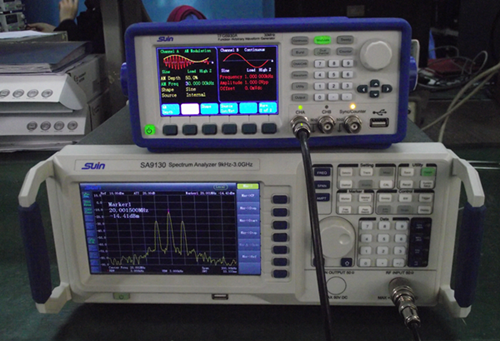
Measure an AM signal and user could observe the frequency and amplitude of modulated carrier and the frequency and modulation depth of AM signal.
Figure 2
From Figure 2 user can observe the result for AM signal, that modulated carrier is 20MHz, carrier amplitude is -14.41dBm, the frequency is 30kHz and modulation depth is 50%.
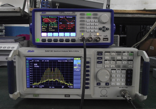
The measurement for a FM signal is same as AM signal, the carrier frequency, the frequency of modulation signal and frequency offset could be observed directly.
3. Measure phase noise
The spectrum analyzers in current market are all available on this function and common difference value method is used to calculate the result. For example, to measure the phase noise if a 100MHz signal offset 10KHz.
Firstly set the central frequency of spectrum analyzer to 100MHz, span to 30KHz, analysis bandwidth to 100Hz. Then move Marker to peak point of 100MHz, open the function of marker difference value and input difference frequency 10KHz and readout this difference value △A. Then use the formula phase noise=△A-10㏒RBW to calculate.
4. Served as simple network analyzer
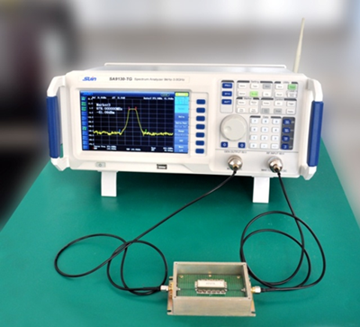
The spectrum analyzer with tracking generator can be served as scalar network analyzer.
For example, use spectrum analyzer to measure S21 of filter. Connect the output port of tracking generator with input end of measured filter and the other output end of filter with RF input of spectrum analyzer, then the S21 of filter could be measured like below picture shown.
Related product information
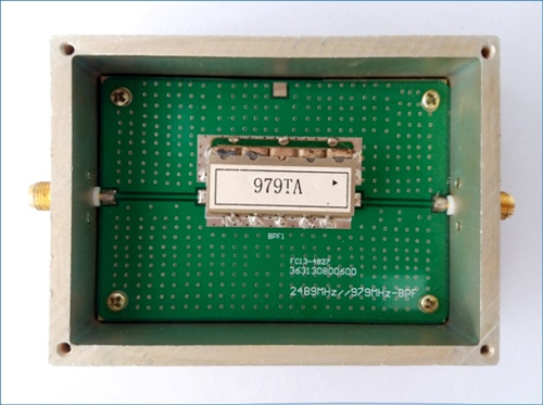
Filter
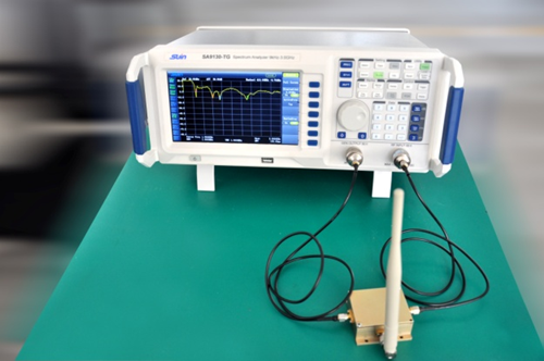
5. Antenna Test with help of tracking generator and the standing wave bridge.
The main purpose is test resonant frequency and SWR of antenna.
Related product information
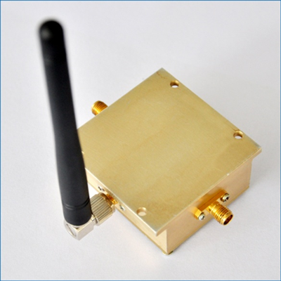
Antenna
6. EMC Pretest
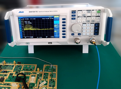
SA9130 has the built-in EMI dedicated 200/9k/120k Hz filter, greater than 15dB low noise amplifier and Quasi-Peak/Average detection mode to meet customers' EMC pretest requirement on the product development and verification stage. So users can detect and resolve problems at the early product development stage that can save time and money for product development and verification fee.
Related product information
Near Filed Probe
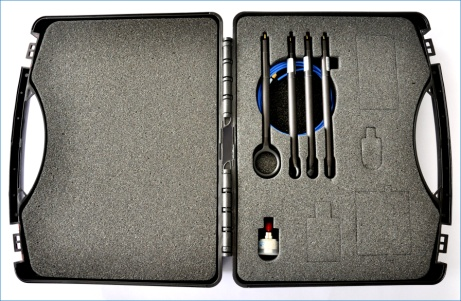
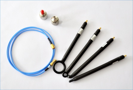
To connect with Spectrum Analyzer
Use the provided BNC-SMB cable to separately connect the SMB Male connector of Probe EM5030-1 and BNC Female connector of N-BNC adaptor, then connect the N Male connector of N-BNC adaptor to RF input of spectrum analyzer.
The connection among Probe EM5030-1, Spectrum Analyzer and tested device like below picture shown.
*Typical Application
Position EMI radiation interference source
Confirm the spectral component's frequency and relative intensity of interference source


没有评论:
发表评论