2022年9月15日星期四

New Arrival - SA5053 Digital Multimeter

A digital multimeter (DMM) is an electronic instrument used for electrical measurement. It can have many special functions like math function and temperature, but the main function is to measure electrical parameters such as voltage, current, resistance, and continuity. As a modern multi-purpose electronic measuring instrument, it is mainly used in areas of R&D, scientific research and education, detection and maintenance, quality test, and automatic production test. Test principle, bandwidth, range, display digit and resolution, and special function measurements are the main factors to consider when choosing a digital multimeter.


Digital Multimeter SA5053


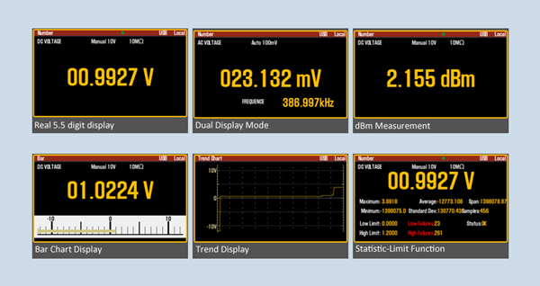
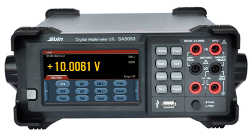
Sun's new DMM SA5053 is a 5.5 digit and dual display digital desktop multimeter that provides rich and powerful features at an economical price. It is designed for the test requirements of high accuracy, multi-function, and automatic measurement. It provides USB Host, USB Device, RS-232, LAN, and GPIB (optional) interfaces for computer-based control. The following will introduce the main features to let you learn it deeply.

1. Real 5½ digits readings resolution (119999 counts).

2. Up to 800rdgs/s measurement speed.

3. True-RMS AC Voltage and AC Current measuring.

4. 4.3-inch color LCD touch screen with double display for easy viewing.

5. Two sets of input interfaces front and rear, which provides convenience to arrange wires.

6. In addition to numerical data display, it also features histograms, trend charts, bar charts, and statistics functions.


Digital Multimeter SA5053 


The new DMM SA5053 will be scheduled to be put on the market in August, if you have any interest or technical consulting, welcome to contact us for more details!

2022年9月8日星期四

Application of Spectrum Analyzer


*Application

ㆍFor the quick check and analysis of Spectral Characteristic

ㆍEMC pretest

ㆍAnalysis and test of characteristics various signals 

ㆍTest systems that requires a very compact instrument

ㆍMeasure the frequency response of cable, attenuator, filter and amplifier


*Customers

ㆍConsumer Electronics

ㆍService and Maintenance

ㆍLab of Universities and College

ㆍMilitary Industries

ㆍTelecom and communications Industries

ㆍManufacturer of RF&MW components


*Application Reference

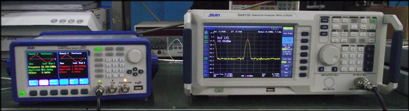
1. Measure a single signal

The spectrum analyzer could be used to measure a Sine, including frequency, amplitude, harmonic and spurious.


measure a single signal by spectrum analyzer

Figure.1. measure a single signal by spectrum analyzer


2. Analyze AM and FM signal characteristics

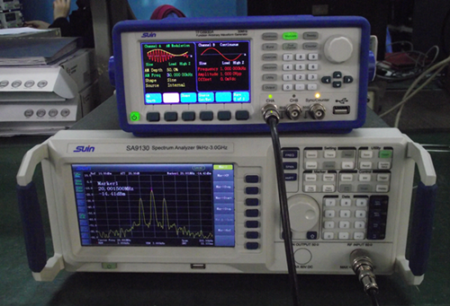
Measure an AM signal and user could observe the frequency and amplitude of modulated carrier and the frequency and modulation depth of AM signal.


Inexpensive RF Spectrum Analyzer

Figure 2


From Figure 2 user can observe the result for AM signal, that modulated carrier is 20MHz, carrier amplitude is -14.41dBm, the frequency is 30kHz and modulation depth is 50%.


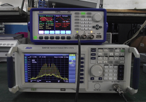
The measurement for a FM signal is same as AM signal, the carrier frequency, the frequency of modulation signal and frequency offset could be observed directly.


Spectrum Analyzer


3. Measure phase noise

The spectrum analyzers in current market are all available on this function and common difference value method is used to calculate the result. For example, to measure the phase noise if a 100MHz signal offset 10KHz.

Firstly set the central frequency of spectrum analyzer to 100MHz, span to 30KHz, analysis bandwidth to 100Hz. Then move Marker to peak point of 100MHz, open the function of marker difference value and input difference frequency 10KHz and readout this difference value △A. Then use the formula phase noise=△A-10㏒RBW to calculate.


4. Served as simple network analyzer

The spectrum analyzer with tracking generator can be served as scalar network analyzer.

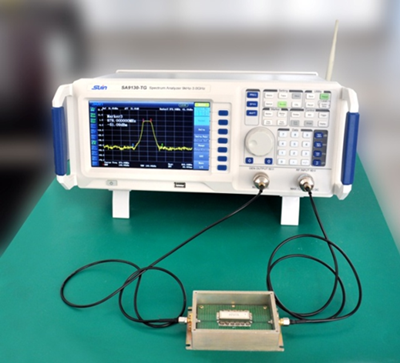
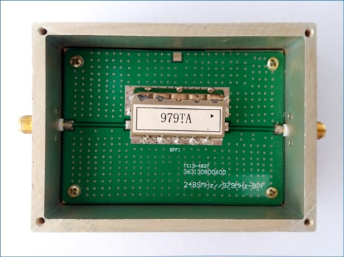
For example, use spectrum analyzer to measure S21 of filter. Connect the output port of tracking generator with input end of measured filter and the other output end of filter with RF input of spectrum analyzer, then the S21 of filter could be measured like below picture shown.


Related product information


Spectrum Analyzer


Application of Spectrum Analyzer

Filter


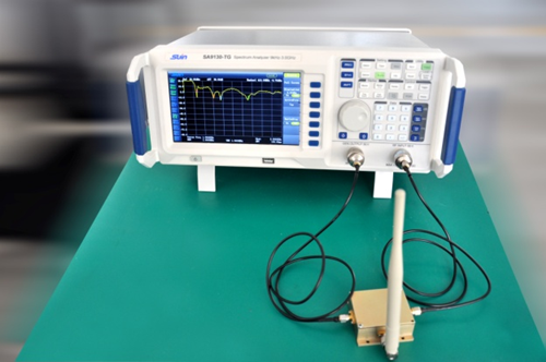
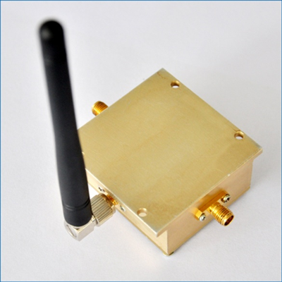
5. Antenna Test with help of tracking generator and the standing wave bridge.

The main purpose is test resonant frequency and SWR of antenna.


Related product information


Application of Spectrum Analyzer


Application of Spectrum Analyzer

Antenna


6. EMC Pretest

SA9130 has the built-in EMI dedicated 200/9k/120k Hz filter, greater than 15dB low noise amplifier and Quasi-Peak/Average detection mode to meet customers' EMC pretest requirement on the product development and verification stage. So users can detect and resolve problems at the early product development stage that can save time and money for product development and verification fee.


Related product information

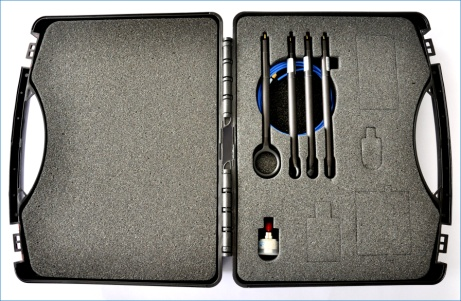
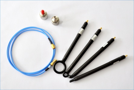
Near Filed Probe


Application of Spectrum Analyzer


Application of Spectrum Analyzer


To connect with Spectrum Analyzer

Use the provided BNC-SMB cable to separately connect the SMB Male connector of Probe EM5030-1 and BNC Female connector of N-BNC adaptor, then connect the N Male connector of N-BNC adaptor to RF input of spectrum analyzer.


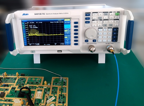
The connection among Probe EM5030-1, Spectrum Analyzer and tested device like below picture shown.


Application of Spectrum Analyzer


*Typical Application

Position EMI radiation interference source

Confirm the spectral component's frequency and relative intensity of interference source

2022年8月27日星期六

Introduction of Crest Factor in Electrical Power System


Definition of crest factor

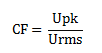
Crest factor (CF) is defined as the ratio of the peak amplitude of a waveform to its RMS value. It is a numerical value without units. When inputting a Sine voltage to a non-linear load, its current waveform will be distorted and the CF value will be more than 1.414. For example, the CF value of current to computer may be up to 2.4-2.6.

Crest Factor reflects the electronic instrument's performance from another view. The bigger its crest factor is, the more rush current will be needed for powering, and the heavier damage will be made to the power grid.


Introduction of Crest Factor in Electrical Power System


Upk: peak value of the waveform

Urms: rms of the waveform


To measure crest factor of Sine

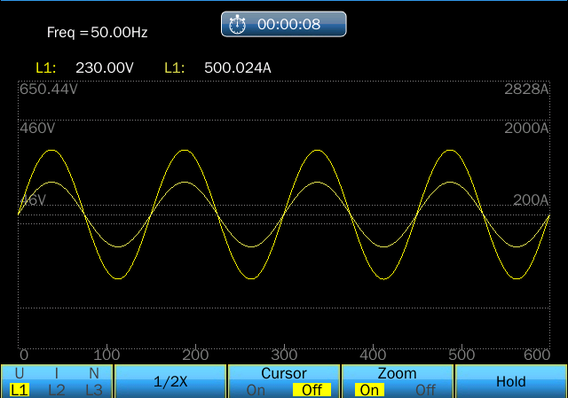
The crest factor of Sine without distortion is . Let's measure it using Suin SA2200 power quality analyzer. Firstly input a 230V/500A/50Hz Sine signal to SA2200 through a calibrator, waveform in scope mode will be shown as Figure 1.


Introduction of Crest Factor in Electrical Power System

Figure 1


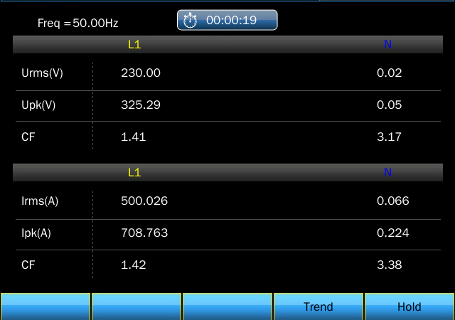
Then voltage and current CF result without distortion will be seen in Volts/Amps/Hertz interface as Figure 2 shown and they are separately 1.41 and 1.42.


Introduction of Crest Factor in Electrical Power System

Figure 2


To measure crest factor of other waveforms

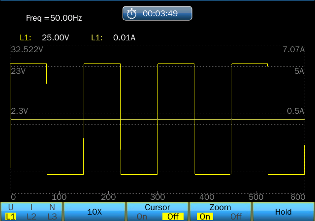
Besides Sine waveform, SA2200 can also measure other waveform's crest factor. Let's take Square as example to see its waveform and crest factor as Figure 3.

Square waveform and its crest factor


Introduction of Crest Factor in Electrical Power System

Figure 3


Bigger current crest factor not only makes extra consumption and other bad effects to the instrument, the generated current waveform distortion can also make pollution to the power grid. So the crest factor of an alternating instrument is as same important as its rms value, and one of the most important parameters to evaluate instrument's performance.


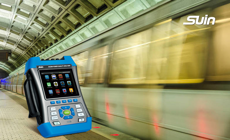
Suin SA2200 power quality analyzer has the basic measuring function of voltage, current and their crest factor. Besides this, it can also measure other parameters, such as dips & swells, harmonics, power & energy, flicker, etc. If you want to know other measuring functions, please kindly contact us.


SA2200 Portable Power Analyzer

2022年8月17日星期三

Brief introduction On How to Select Power Quality Analyzer

The definition of power quality - is the deviation of voltage, current, or frequency that lead to electric equipment’s breakdown or abnormal work, which contains: frequency deviation, voltage deviation, electromagnetic transient, power supply reliability, waveform distortion, three-phase imbalance, voltage fluctuation, flicker and so on.

The power quality analyzer is a portable device that could test and analyze the running quality of the power grid. It could provide harmonic and power quality analysis during power processing, and also are able to offer a long-time data collection and monitoring. Meantime, with help of matched PC software, it could analyze the data uploaded to the PC.

For the past few years, because of the impact of the frequency converter and variable load on the power grid, the difference of power quality in grid become huger, so more and more industrial clients would like to select and buy power quality analyzer to carry out self-assessment of power quality and prevention.

Then how to select a suitable power quality analyzer?


Firstly, select ones which can meet international and national standards according to the actual requirement. International Electrotechnical Commission abbreviated IEC especially issues the IEC61000-4-30 standard for power quality. Referring to IEC standard and to meet China actual situation, we classify this standard and issue national power quality standard GB/T 12325/15945/15543/12326. Meanwhile, due to the electronic instrument limit, even if the same data is tested by one test instrument, there will be deviation in the result. And if a serious deviation occurs, it will lead to bad results during issue verified report. Considering this factor, IEC makes the IEC62586 standard which defines strictly the uncertainty requirement for instrument repeat testing. Therefore, the power quality analyzer which is designed as IEC61000-4-30 standard and already passes IEC62586 certification will be the best choice for the user.
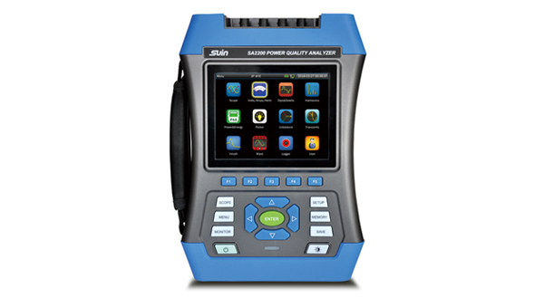

power quality analyzer   


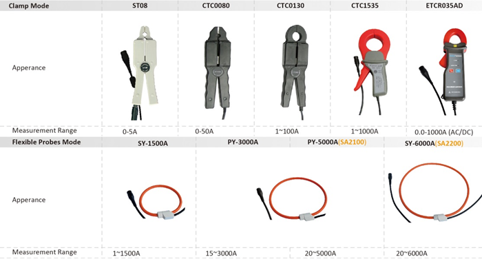
Secondly, proper voltage range and accuracy could selectable for user according to the actual measured voltage and current. Currently, the main voltage limitation in market is 1000V or 600V, while current selection based on the different current clamps or rogowski coil configuration and range 10A, 500A, 3000A or 6000A will be popular ones.
 

Brief introduction On How to Select Power Quality Analyzer


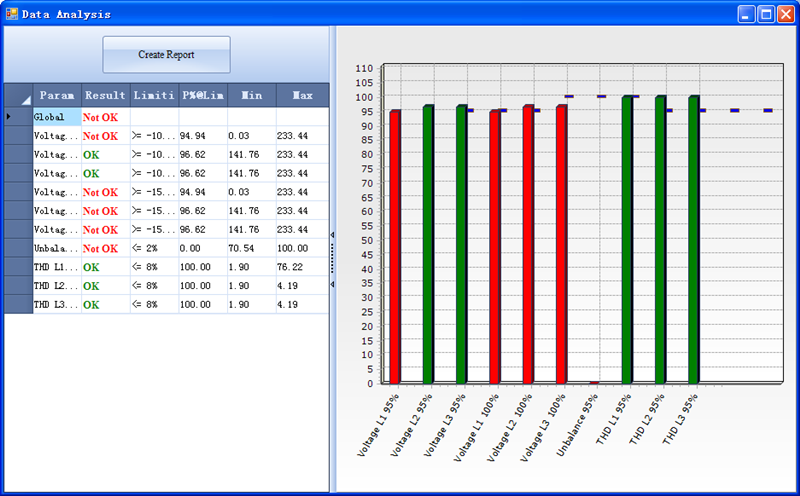
Thirdly, the convenience of matched PC software is also very important. Because a lot of test points are referred and larger data volume to be processed, strictly speaking, it is required to test one week for each point. So how to issue a standard conformity report, analyze the default point in detail and set the trigger mode, will affect the operator’s working volume and difficulty level to solve problem. Therefore, the convenience of PC software attracts greater attention from manufacturer of power quality analyzer to increase device’s competition.
 

Brief introduction On How to Select Power Quality Analyzer


Fourthly, the application scene of power quality analyzer should specify clearly before purchase. The common frequency setting is 50Hz when use power quality analyzer. While 400Hz setting will be needed when use power quality analyzer carry out measurement for avionics and shipboard systems. At this time, the power quality analyzer compatible both 50Hz and 400MHz will be best choice.

In addition, most instruments in the market reach to IP50 protection grade only in dustproof protection, while measurement performed in heavy humidity area, power quality analyzer with higher protective level IP65 which contains both dustproof and waterproof will be considered.


Product Recommendation

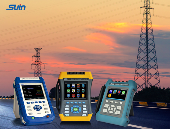
Suin power quality analyzer SA2100/SA2200 totally conforms to IEC61000-4-30 standard,

separately meet Class S or Class A accuracy according to different usage. They can measure and calculate flicker, voltage dips and swells, interruption, transient, unbalance, harmonic, interharmonic, signal voltage, RMS, power, power factor and energy, etc. With characteristic of high quality, portable, convenient software, IP52 grade and 400Hz measurement, they are also good choice for user when buy power quality analyzers.

power quality analyzers


They can help engineers and electronic technicians to quickly find and analyze all power quality parameters in fields of power grid, machine manufacturing, electronic manufacturing, process industry, metallurgy and petrochemical, rail traffic, construction, energy saving, etc., so that to guarantee safe production, energy saving and cost reduction.
2022年8月8日星期一

How to Select A Suitable Stopwatch Calibrator


Types of stopwatch

A stopwatch is a time measuring device that’s commonly used in our everyday life, usually, it is divided into three types - digital, mechanical, and electrical. And currently, the most common ones we can see in the market are 401/405/407/408 pointer electrical stopwatch, 411 digital millisecond meter, 415/417/417B digital electrical stopwatch.


Tips to select a stopwatch calibrator

Instruments that can calibrate stopwatches are named stopwatch calibrators, usually working together with a fixture. It can make a stopwatch start, stop or return to zero adopting the control circuit and output circuit, with OCXO as the standard time source, so as to achieve the aim of calibrating stopwatches. Here are some tips to select stopwatch calibrators as follows for your reference:

1. National standard

SF2002 Stopwatch Calibrator is totally designed according to China JJG237-2010 Standard. If you need another national standard, please firstly compare it with this.

2. High accuracy OCXO

OCXO is built in the stopwatch calibrator and it is important for time intervals. The higher accuracy it has, the better it is. SF2002 Stopwatch Calibrator adopts 10MHz OCXO with accuracy≤5×10⁻⁸, which is higher than the one specified in JJG237-2010 Standard. In addition, it has excellent second stability and aging rate, which is more helpful for long time calibrating.

3. External frequency standard

Although the OCXO in a stopwatch calibrator is very accurate for calibrating stopwatches or timers, sometimes higher accuracy is still needed in the actual calibrating job, therefore, a stopwatch calibrator with an external frequency standard will be a better choice.

Fortunately, the SF2002 stopwatch calibrator reserves a 10MHz input terminal in the rear panel to meet this requirement. Please switch the Nominal Frequency at the rear panel to EXT, and input a 10MHz signal with 0V-0.5V (Low)& 3.3V-5V(High) amplitude, then SF2002 can make higher accuracy calibration.

4. To calibrate more kinds of timer/stopwatch

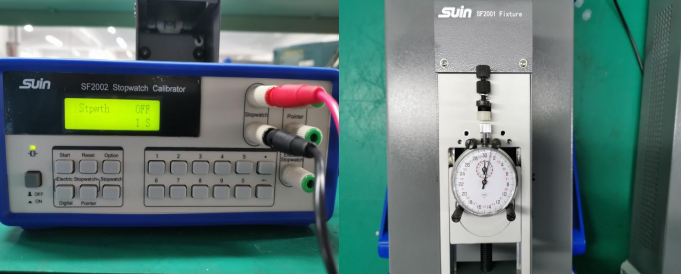
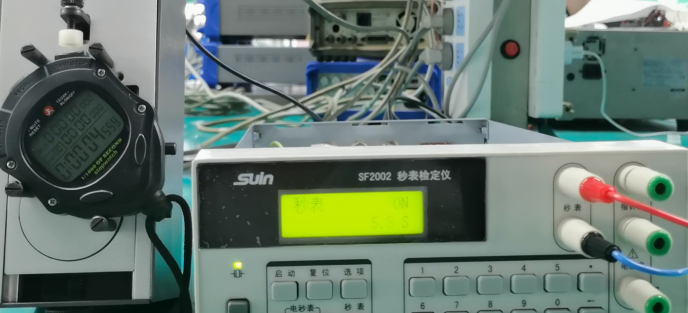
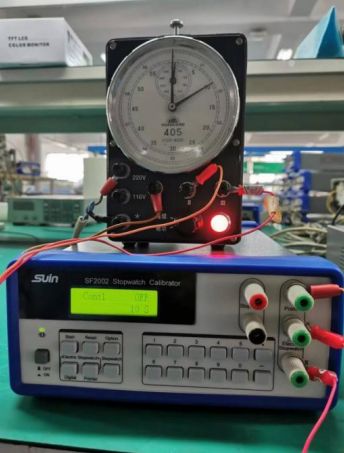
This is a very important factor for users to consider when selecting a suitable calibrator. The following pictures will take you to see the real working status when SF2002 calibrates different stopwatches.


① To calibrate mechanical stopwatch


 How to Select A Suitable Stopwatch Calibrator


② To calibrate digital stopwatch


How to Select A Suitable Stopwatch Calibrator


③ To calibrate pointer electrical stopwatch -405 timer


How to Select A Suitable Stopwatch Calibrator


If you need more specification or technical support for this product, welcome to contact Suin. As a specialist in electrical test and measurement instruments, Suin team will do its best to meet all of your needs.

2022年7月30日星期六

How to Test the Frequency Response by SA1140C Frequency Characteristic Analyzer?

In electronic testing, we always need to test the resistance characteristic and transmission characteristics of the electric circuit. Transmission characteristic includes gain and attenuation, amplitude-frequency characteristic, phase-frequency characteristic, etc. The instrument to test these characteristics is called a frequency characteristic analyzer, simply named frequency sweeper. It is really a good helper for adjusting, calibrating, and troubleshooting the electric circuit not only in education but also in research and development. 


Now we’ll take SA1140C Frequency Characteristic Analyzer as an example to demonstrate how to test the frequency response of an RC circuit.


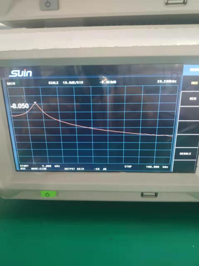
Before testing, SA1140C should be calibrated firstly by pressing [CAL] key, then set as follows:

• Output gain   -30dB

• Start             5kHz

• Stop             100kHz 

• Impedance    500k


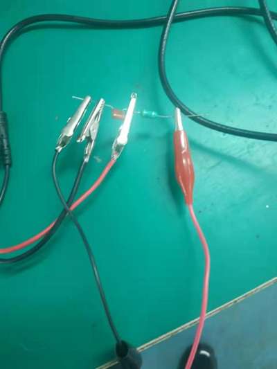
And then connect the RC circuit as below picture shown: 

• C=15 nF   

• L=4.7mH   

• f=20.200kHz


How to Test the Frequency Response by SA1140C Frequency Characteristic Analyzer?cid=191


The measuring result will be displayed in SA1140C as below picture:


frequency characteristic analyzer


You can also measure the frequency response of the LC resonance circuit or low pass filter according to the above set and operation.


If you want to know more about the SA1140C Frequency Characteristic Analyzer, please check its specification on Suin website or contact us directly.

2022年7月22日星期五

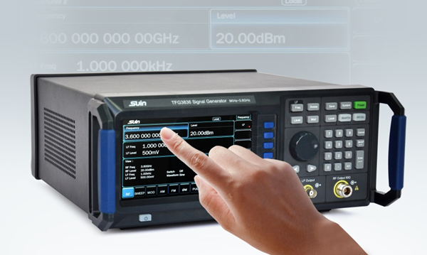
New Launch - TFG3836 3.6GHz RF Signal Generator

Suin launches new RF signal generator TFG3836 at the beginning of this March after market research and engineers’hard work.


RF signal generator is the instrument that’s especially used to produce RF signal, currently, most vector signal generators are also in RF band, so it’s called vector RF signal generator. Generally speaking, the simple RF signal generator is used to perform carrier tests while the vector signal generator is mainly for the digital signal tests.


When choosing the RF signal generators, factors such as frequency range of output signal, modulation type, frequency stability, amplitude accuracy, required power size, etc should be considered. According to this, let’s see the features of TFG3836.


1. Frequency range up to 3.6GHz


2. Wild range of level output

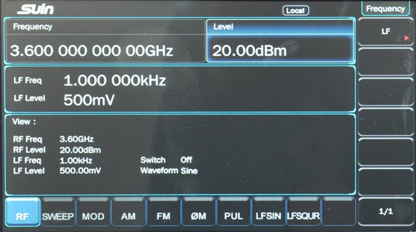
The maximum output level up to +13dBm (nominal value), maximum +20dBm is settable to meet the nonlinearity test of the amplifier.


图片1_副本.png


3. Higher level accuracy

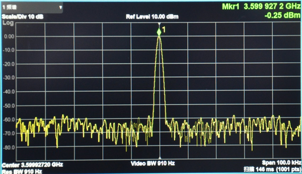
The typical accuracy of output level could be up to 0.5dB, which could provide the user with accurate excitation signals.


图片2_副本.png


4. Lower phase noise

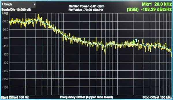
Higher signal purity and the typical phase noise can reach < -105dBc/Hz@20 kHz. The better the high-stability clock reference is selected, the better phase noise capability will get.


图片3_副本.png


5. Full frequency and power sweep capability


6. Rich modulation function

Provides standard AM, FM, φM, and Pulse modulation, all supporting internal and external modulation.


图片4_副本.png


7. Powerful pulse modulation function

A high-quality pulse modulated signal could be provided. The typical rise/fall time could be 10ns and an on/off ration greater than 70dB. Both internal and external modulation can be supported. The built-in pulse generator could generate pulse sequence and output it as a separate pulse generator


8. Multi low-frequency output

DC, Sine, and Square can be output from the LF port to be used in different simulation tests. At the same time, the LF signal is independent of the internal modulation signal, which equals to provide two independent RF and LF signal generators to the application.


9. 7 inches TFT capacitive touch screen, simple and easy to operate.


RF Signal Generator


All mentioned functions are standard configurations, also supplied with the most competitive price. Compared with similar products in the current market, TFG3836 will be a better choice for educational laboratories, industrial production lines, R&D applications.

Power Quality Analyzer: The Modern Solution for Electrical Reliability and Efficiency

  https://www.suindigital.com/power_quality_analyzer/825.html In an increasingly electrified world, maintaining the stability and performanc...